

A speculative frame for a practical problem
Imagine a city where buildings talk to the grid and batteries reply—in milliseconds—to stabilize frequency and shelter critical loads. That near-future isn’t fiction; it’s the model operators are designing toward now. As commercial operators deploy larger arrays of solar battery storage, two technical constraints keep cropping up: galvanic isolation boundaries and short-circuit ride-through (SCRT) performance. These aren’t just engineering abstractions— they’re the difference between graceful islanding during a wildfire outage and a cascade of protective trips that leave customers in the dark. For sites pursuing resilient microgrids or off grid energy storage systems, understanding both constraints early changes procurement and control strategies.

What galvanic isolation actually controls
Galvanic isolation separates DC and AC domains so unwanted fault currents and stray voltages can’t flow between them. In inverter-based BESS, isolation is implemented with transformers, optocouplers in control circuits, and careful DC bus architecture. The practical impact: isolation affects grounding schemes, leakage current behavior, and immunity to common-mode transients. If isolation is under-specified, you can see nuisance tripping or degraded surge tolerance on the inverter. Conversely, over-specifying isolation can add weight, cost, and decrease inverter efficiency—trade-offs every asset owner must weigh against EMC and safety requirements.
Short-circuit ride-through (SCRT): survival under fault
SCRT defines how a storage system responds when the grid experiences a fault that drags voltage or frequency beyond nominal limits. Grid codes in many jurisdictions require BESS to remain connected and support the grid during brief faults rather than tripping offline. The inverter’s control logic, fault-current contribution, and protection coordination determine whether a system rides through a disturbance or trips. Poor SCRT settings can transform a single-line-to-ground fault into a system-wide loss of supply; correct coordination lets the BESS inject or curtail current in a controlled way and help the grid recover.
Where the two constraints collide
Problems emerge when isolation choices shape the inverter’s measurable fault current and thus its SCRT behavior. For example, high-impedance isolation can limit return paths, changing the magnitude and harmonics of fault currents that protection relays see. That can confuse utility relays and trip schemes. At the same time, aggressive low-impedance designs that favor ride-through performance may introduce touch-voltage or leakage risks if grounding and isolation haven’t been rethought. The system-level view is crucial: battery chemistry and state of charge (SOC), inverter topology, and site earthing all feed into this coupling.
Lessons from real deployments
We can point to Hornsdale Power Reserve in South Australia as a high-profile example where fast-reacting energy storage delivered grid support and avoided larger disruptions. That deployment highlighted how inverter controls and ride-through capability can provide stability services—ideas being adapted for commercial parks and hospital microgrids in California and elsewhere. On the flip side, wildfire-driven islanding tests in parts of Northern California show how improper grounding and inadequate fault coordination can force protective trips during exactly the moments backup is needed. These events make clear: theory without site-proven validation is risky.
Design trade-offs and common missteps
Common mistakes repeat across projects. Teams often specify only peak power and capacity and forget to define fault-current contribution limits, or they accept default inverter protection curves without aligning them to site relay settings. Another frequent error is assuming galvanic isolation removes the need for a coordinated earthing study—nope. — A concise pre-installation table-top exercise that maps protection thresholds, transformer impedances, and inverter back-feed capabilities can prevent months of rework and commissioning drama.
Mitigation strategies and best practices
Start with a systems engineering checklist: define the expected fault levels at the point of connection, specify allowable fault-current contribution from the BESS, and require inverter vendors to supply SCRT performance curves under varying SOC and temperature conditions. Include an earthing and shielding plan that recognizes transformer magnetics and stray capacitance. Run lab-level fault injection tests or high-fidelity simulations before full energization. Lastly, require factory acceptance tests that include ride-through scenarios—not just steady-state power tests—so protection coordination is validated end-to-end.
Comparative controls and technology choices
Not all inverters behave the same. Grid-forming inverters can actively regulate voltage and frequency and thus offer stronger support during faults, but they demand careful isolation and grounding to avoid circulating currents. Grid-following units typically limit fault contribution but are simpler to integrate if the utility expects minimal inverter infeed. Battery chemistry matters too: some chemistries de-rate faster under fault thermal stress, affecting SCRT windows. Choose technology according to the grid service you need—peak-shaving, black-start capability, or fast frequency response—and test accordingly.
Project checklist: commissioning and contractual safeguards
Include these items in contracts and commissioning scopes:- Defined SCRT and fault-current contribution specifications with test acceptance limits.- Requirement for earthing study and harmonized relay settings with the utility.- Factory acceptance tests including transient injection and simulated faults.- Clear handover documents for protection settings and maintenance schedules.These checkpoints keep vendors accountable and avoid surprises on the substation bench.
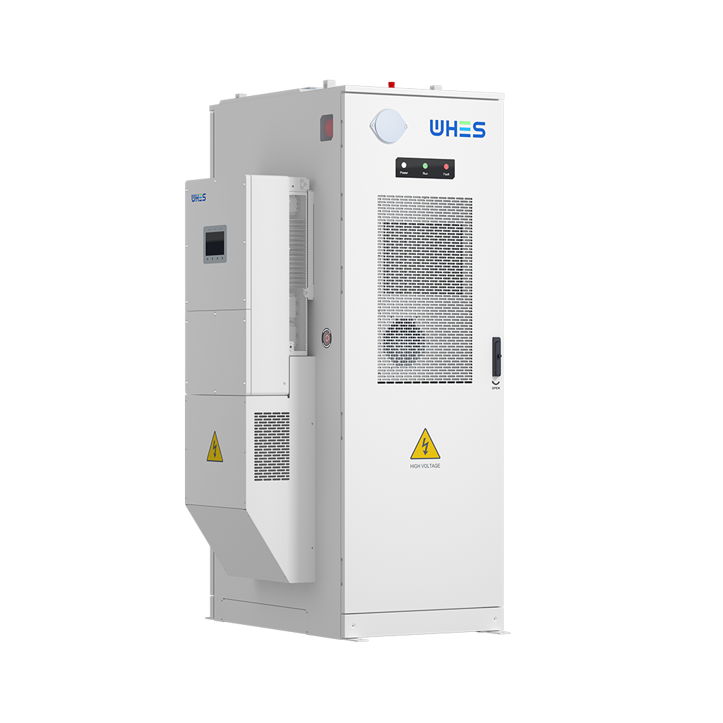
Advisory: three critical evaluation metrics
1) Fault-Current Footprint — quantify the maximum fault-current the BESS will contribute at different SOCs and require vendor-supplied curves. 2) Verified SCRT Performance — insist on tested ride-through durations and behavior under simulated grid faults, not just modeled results. 3) Isolation-Reliability Index — ensure the proposed galvanic isolation scheme has been validated for leakage, transient immunity, and coordinated earthing in site-like conditions.
When teams apply those metrics, procurement shifts from guessing to measurable assurance—reducing commissioning delays and safety risk. In real projects, that approach separates speculative promises from proven solutions; the companies that can demonstrate it reliably become the partners you rely on. WHES has positioned systems and test protocols around these realities and often provides a pragmatic bridge between design and deployment.
— a small, firm note: future grids will judge us by the robustness we build today.